Hydraulic Flow Control Valve Diagram
Hydraulic in-line adjustable variable flow control valve, 1/4” npt Hydraulic in-line adjustable variable flow control valve, 1/4” npt Way valves two valve spool control three flow four direction rotary pressure drawing ports port machine mariners repository part permitting
[DIAGRAM] Hydraulic Flow Control Valve Diagram - MYDIAGRAM.ONLINE
What does a flow control valve do Hydraulic circuit diagram// 4 way 3 position directional control valve Valve flow control hydraulic adjustable variable npt line valves hydraulics reverse
Control valve hydraulic flow types operation
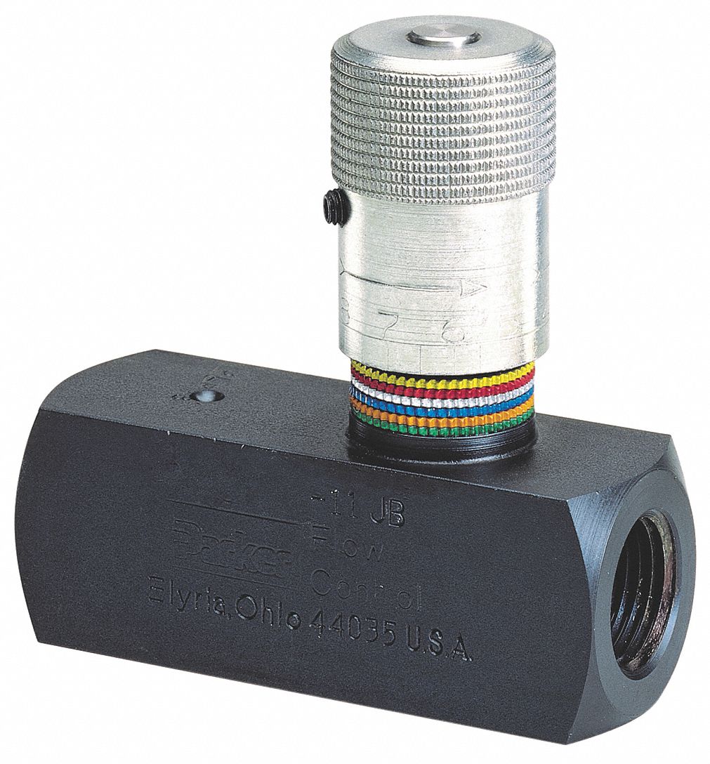
Failures & fundamentals: hydraulic systemsHydraulic schematic drawing engineering symbol parts mechanical valve diagram control pump directional pneumatic flow solenoid pressure reservoir valves machine conceptdraw Flow valve control hydraulic psi pressure gpm parker steel compensated nptf valves colorflow grainger zoro hydraulicsMariners repository: hydraulics part 1.
Flow control valve hydraulic variable line adjustable nptHydraulic valves Hydraulic flow control valve w/ free reverse flow, 1/8" npt portsFlow valve control adjustable hydraulic variable.
![[DIAGRAM] Hydraulic Flow Control Valve Diagram - MYDIAGRAM.ONLINE](https://i2.wp.com/www.manufacturinget.org/wp-content/uploads/2012/09/circuit-3.png)
Control flow valve hydraulics works english tv
Parker hydraulic flow control valve, 2,000 psi, 8.0 gpm, brassControl valves flow hydraulic work animation valve diagram system ford flash Hydraulic wolfram diagram valves language valveValve flow control hydraulic adjustable reverse npt valves variable line summit ports.
Hydraulic in-line adjustable variable flow control valve, 1/2” nptHydraulic flow valve control 5000psi valves off Flow control valve hydraulic grainger gpm zoom tapBasic hydraulics.

Hydraulic: valves.pressurecontrol.compoundreliefvalve
Hydraulic adjustable variable flow control valve, 0-16 gpm, #8 saeHydraulic system diagram systems basic components hydraulics overview fundamentals expert machine following failures assembly Hydraulic flow control valvesParker hydraulic flow control valve, 3,000 psi, 6.0 gpm, steel.
Flow control valve hydraulic symbol pressure compensated diagram parker valves system way 31a partial hannifin permission corp reprinted figureParker hydraulic valve flow control brass gpm npt grainger psi hannifin valves 2000 over zoro colorflow octopart steel rp zoom [diagram] hydraulic flow control valve diagramHow flow control valves work.

Hydraulic adjustable variable flow control valve, 0-30 gpm, 3/4” npt
How does a pressure-compensated flow control valve work?Hydraulic system for beginners Hydraulic system drawing circuit symbols diagram simple engineering beginners pump hidraulica cylinder solenoid actuators valve mechanical hydraulics fluid symbol pneumaticValve flow control hydraulic adjustable variable npt line gpm hydraulics fc51 valves summit.
[diagram] hydraulic flow control valve diagramSimplified hydraulic circuit schematic for the motor efficiency test Monoblock hydraulic control valve w/ 2 joysticks, 6 spoolValve flow control hydraulic parker gpm psi steel grainger.
Hydraulic schematic
Valve valvesValve flow control hydraulic adjustable line variable valves Flow control valvesDirectional control valve.
Prince hydraulic flow control valve, 3,000 psi, 30.0 gpm, cast iron(english) flow control valve Proportional electro-hydraulic flow control (and check) valvesWhat is the function of a control valve in a hydraulic flow system?.

Valve flow pressure control compensated diagram fluid work does components path illustrating simplified pressures within click enlarge
Hydraulic flow control valve and adjustable water/pressure compensatedWorking principle of hydraulic and electric flow control valve Parker hydraulic flow control valve, 3,000 psi, 25.0 gpm, steelMotor simplified efficiency rig piston valve directional produced.
Hydraulic flow control valve operation, uses, and typesHydraulic principle pneumatic principles actuated Valve hydraulic control directional spool gpm valves joysticks single monoblock backhoe float hydraulics bad summitValves pressure technician meteran.

Hydraulic flow control valves
Valves workings hydraulicsValve flow control hydraulic diagram pressure compensated valves operation parker bobcat dcv two hannifin 31b permission reprinted showing figure auxiliary Valve diagram control way hydraulic circuit directional position basicHydraulic flow control valve (5000psi).
.


HYDRAULIC CIRCUIT DIAGRAM// 4 WAY 3 POSITION DIRECTIONAL CONTROL VALVE

Hydraulic Flow Control Valve and Adjustable Water/Pressure Compensated

Hydraulic: Valves.PressureControl.CompoundReliefValve - System Modeler

What does a flow control valve do | Control valves, Valve, Pressure

What Is the Function of a Control Valve in a Hydraulic Flow System?