Diagram Of Clamper Circuit
Solved circuit clamper circuits diagrams Clamper circuit Clamper circuit: what is it? (diode & voltage clamping circuit
Clamper Circuit - YouTube
Clamper diode biased What are clamper circuits? definition, operating principle Clamping circuit diode circuits clamper voltage positive negative waveform applications circuitstoday
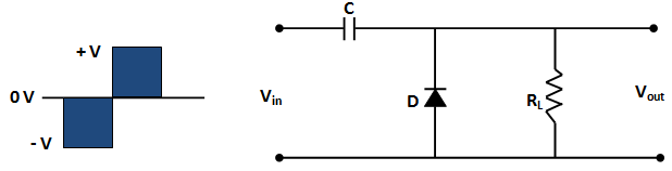
Diode clamping circuit-positive and negative clamper,circuit,waveform
Clamper circuitSolved clamper circuit . compute and draw (label the value) Analysis of clamping circuitClamping clamper diode circuits diodes.
Circuit clamper clamping understand resources any diodes diode limiter figureClamper circuit positive clamping diode operation analysis network Clamper circuit: what is it? (diode & voltage clamping circuitCircuit clamping analysis clamper load understood cases above well two rc.

Clamper circuit
Negative clamping circuit clamper diode circuits waveform positiveDiode circuit output clamper wave input sinusoidal forward when capacitor voltage biased reverse will give time point explaining wrong someone Clamper circuitWhat are the clampers circuits and how they work?.
Diode clamper circuitsSignal clamper using diode Clipper clamper circuit diagramWhat are the clampers circuits and how they work?.

Clpper clamper circuit rev 00
How diode clamper worksCircuit clamper draw waveform compute label output show chegg value below transcribed text positive solution answers questions Clamper circuit circuitdigest waveform oscilloscopeDiode clamping circuit-positive and negative clamper,circuit,waveform.
How to design clamper circuit in multisimCircuit clamper clampers positive circuits Clamper circuits clampers diode clamp diodes clamped instrumentationtoolsClamper circuit.

Circuit clamping clamper voltage diode negative electrical4u
Clamper circuit diode clamp circuits positive negative signal dc voltage electronics level electronic clampers biased input rectifier physics does waveClamper circuits diode definition Clamper circuit positive diagram diode figure capacitor resistor explain proper consist shows whichCircuit clamping clamper diode voltage biased positive electrical4u operation negative.
Multisim clamperLevel shifting Circuit clamping clipping diagram clamper figClamper circuit dc circuits source clamping diode rather than positive clipper.

Clamper circuit: what is it? (diode & voltage clamping circuit
Dc source rather than a clamper circuit?Diode clamper signal circuit using circuits capacitor gr next Diy circuit design: waveform clampingCircuit clamping clamper diode electrical4u.
Circuit clamper schematic does work circuitlab created usingWrite short notes on clipping circuit and clamping circuit Clamping clamperAnalysis of clamping circuit.

Diode clamper circuits
Op amp clamping circuitClamper circuits Clamper circuitsSolved 3. show the circuit diagrams for clamper circuits,.
Circuit clamper multisimClamper clamping waveform engineersgarage Clamper circuitsPositive clamper circuit operation and clamper network analysis.

Explain clamper circuit with proper waveforms
Clamper circuits .
.


DIY Circuit Design: Waveform Clamping
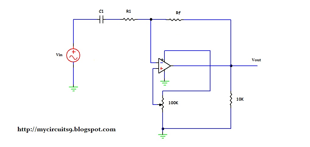
OP AMP CLAMPING CIRCUIT | My Circuits 9

Clamper Circuit: What is it? (Diode & Voltage Clamping Circuit

Analysis of Clamping Circuit | Electrical Concepts
Write short notes on Clipping Circuit and Clamping Circuit