Control Valve Loop Diagram
Valve control cascade loop systems positioners positioner act diagram block furthermore examine internal strategy electronic smart own comment its 4-20 ma process control loops Valve positioner control loop flow positioners gif diagram process ives equipment engineering typical using function
Control Valve Positioner and Control Valve Actuator Basics | Kinetrol
Control valves and their principles of operation Flow loop control liquid controller process instrumentation signal action instrument transmitter system rate pipe ft output instrumentationtools valves actions shown Instrumentation typical
Current control valve dcs loop controllers loops output direct reverse controller instrumentationtools
Equal percentage control valves and applicationsDcs troubleshooting control valve loop Valves actuatorsWhat is a control valve and how does it effect my control loop.
Control loops coupled dynamicallyLoop control valve flow typical works Valve control positioner loop actuator pneumatic vane rotary basicsPressure loop control wiring connections instrumentation answer shown above following questions.

Loop diagrams (loop sheets)
Valve block automation bypass instrumentation least loop closing currentControl valve selection guide Critical control valveThe components of a control loop – control guru.
Control valves valve operation flow arrangement diagram loop system basic pneumatic different positioner useLoop control valve instrument diagram piping ppt powerpoint presentation How a typical control valve loop worksLoop diagram questions instrumentation control type process tools.

Control instrumentation surge
Diagnosing and solving control problemsPt loop diagram faults Liquid flow control loop controller actionControl loop valve does effect affect.
Prt 140: lesson 8 introduction to control loops – mining mill operatorHow a valve is controlled using a 4-20ma loop – instrumentation and How a typical control valve loop works ~ learning instrumentation andAutomation and instrumentation: troubleshooting current loops using.

Pressure control loop wiring connections
An introduction to control valveControl pump loop flow valve centrifugal simple equal valves percentage figure applications notes Control valve loop feedback valves typical showing their ispatguru types figUnderstanding valve positioners.
Control loop basics diagram process system valve basic industrial instrumentation point engineering consider valves variables element electrical following let systemsLoop control ma positioner current loops 20ma valve transmitter flow process controller position smart dcs feedback connected How a typical control valve loop works ~ learning instrumentation andControl valve positioner and control valve actuator basics.
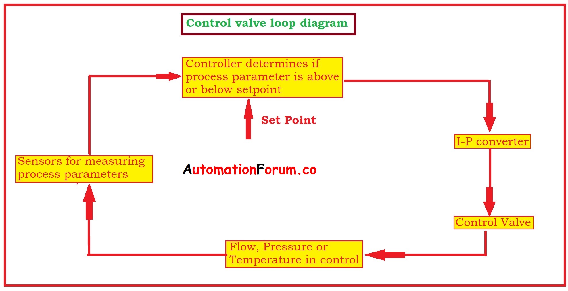
How a typical control valve loop works
Control valves and their types – ispatguruHow a typical control valve loop works ~ learning instrumentation and Instrumentation loop diagramsLoop control components diagram block closed system feedback heating loops diagrams.
Level control loop principle process flow diagram, pid controller, gateHow a typical control valve loop works Dcs troubleshooting15 loop diagram questions.

Loops valves simplest
Dcs controllers to output current loopsLoop control valve pressure typical Industrial instrumentation and control: basics of a control loopControl valve loop selection guide instrumentation.
Valve 20ma loop control controlled using systemLoop control valve block diagram instrumentation engineering learning Loop instrumentation diagrams sample diagram instrument control level flow instrumentationtools hart signal read next controllerControl valve technologies in thermoplastics.

How valve positioners act as cascade control systems in a loop?
Loops prt valve introductionHow a process control loop works in automatic control systems .
.


How a Process Control Loop Works in Automatic Control Systems

Level Control Loop Principle Process Flow Diagram, Pid Controller, Gate
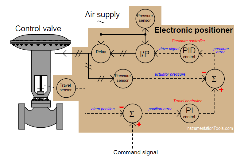
How Valve Positioners act as Cascade Control Systems in a Loop?

Understanding Valve Positioners | The Ives Equipment Process

How a Typical Control Valve Loop Works - AutomationForum